Space plasma experiment "Shadow" - Frequently asked Questions
| Information from TsNIIMASH website |  |
What Amateur radio equipment is present onboard ISS?
The nomenclature and the basic characteristics of the onboard Amateur radio equipment on ISS, are described in the publication: "На борту международной космической:", Радио, 2001, № 4, с. 59 (in Russian) and on Web-pages of ARISS and AMSAT - public organizations supporting Amateur radio activity on ISS. General features of the available antenna system are presented below.
Four regular VHF and HF aerials are mounted on the Service module by the crew of the third expedition, as shown in figure:
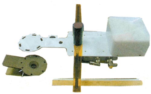
The aerials are located on a cylindrical surface of the service module at an angle of 90 degrees to each other. Each of four established antenna systems has a log-periodic aerial of 1 … 2,5 GHz band and a flagpole HF or VHF aerial connected to a diplexer, as shown in figure:
Photo in Fig. 6 shows one of four antenna systems. The log-periodic microwave aerial with a protective cap is mounted on the right of a plate. In its centre there is a fastening element for the HF or VHF flagpole and also you can see a "clothes-peg" for fastening of the plate to a handrail on a surface of the service module. Diplexer is mounted under the plate.
Three antenna systems are identical (include microwave aerial and flagpole on a range of 144 and 432 MHz), and the fourth differs by that the aerial on a range of 10 m is established instead of VHF aerial.
Antenna system photo.
The detailed information on it you will find on ARISS home page and at http://sarex.gsfc.nasa.gov/~ariss/Netherlands00/Attachment%2020_files/v3_document.htm.
The already available amateur radio equipment allows to run "cold" (with no plasma injection) experiments just now.
What type radio do I need?
Typically any packet radio that you already have available. Actually you need only a shortwave receiver to join the experiment. Antenna and, generally, the problem how to equalize network sensitivity, is a subject of further discussion. The simplest vertical flagpole antenna may be a proper choice.
"Cold" experiments what for are necessary?
The SpEx "Shadow" will be performed in two stages:
- of "cold" (with no plasma injection) training seances and
- of full scale "hot" (with plasma injection) experiments.
The purpose the "cold" stage is to specify all procedures and to check readiness of the receiving network. Besides we can evaluate an actual pattern of the onboard beacon antenna and so to collect the reference knowledge for the "hot" stage. While performing "cold" seances it seems interesting to see Shuttle’s shadow with Shuttle being docking or docked to ISS.
Being lucky and fast in managing of the receiving network, we may begin the "cold" stage probably this year on the International Space Station.
After successful fulfillment of the "cold" training and reference phase it will be possible to accept the justified solution on realization of a series of full scale "hot" experiments probably an year later.
Why the expected shadows’ forms in figure 2 looks so strange?
Because sounding signals of various frequencies dissipate in various parts of a plasma jet. The higher frequency, the more dense should be plasma, where the sounding signal can dissipate and, accordingly, the more deeply it will penetrate into a plasma jet, since density in the jet is the greatest at an exit of a source and sharply falls down to periphery.
For every plasma plume in free space one may define at least two zones of expansion in dependence on predominant mechanisms and degree of interaction of injected substance with the main dynamical factors of space flight, namely the Earth magnetic field and the environment.
The inner zone corresponds to non-perturbed expansion of relatively dense plasma flow core at the exit of the source where the plasma density and pressure are much greater than the density of the environmental media and the magnetic pressure. In other words the artificial plasma in this zone does not "feel" neither magnetic field nor environment. Here the plasma expands almost as an ordinary neutral gas in emptiness, i.e. as a rather narrow axis-symmetrical cone, which disseminates high-frequency radiation (in our forecast 2400 MHz) so, that border of the radio shadow, formed on the Earth surface, looks almost circular.
The outer zone of the flow expansion corresponds to the condition when the magnetic pressure already exceeds the plasma pressure so that its expansion across the magnetic field is inhibited. It is so arranged in the Nature, that the plasma, i.e. mix of equal amounts of ions and electrons can freely move along force lines of a magnetic field and very reluctantly across. As a result the plasma plume obtains a form of three-dimensional "petal" being oriented along the Earth magnetic field.
In this zone the signals of less high frequencies (in our forecast 144 MHz) dissipate, and the border of the radio shadow, formed on the Earth surface, should be also extended along a magnetic meridian.
However, figure 2 is only an expectation, and how it will look actually we can find out, if we shall do this job together.
Notice, that the expected effect of the radio shadow has a continental scale, therefore it is desirable to manage a few "measuring" fields also of continental scales to see the picture of wave scattering in whole and in different conditions.
How the log-file (record) of experiment’s session will look and What to do with this log-file?
It depends on the method of sounding signals generation which will be chosen after a proper discussion. One such method was proposed and demonstrated by Vjacheslav Batuchtin (RV3DGA). He proposed to transmit a sounding signal (the onboard beacon) as a permanent sequence of packets of minimal duration and simple format, say, as follows:
RS0ISS, 12.23.45, 06.12.02.
Any ground Amateur Radio operator will begin to record the log-file of experiment’s session as ISS appears at the local radio horizon. Every operation session would take 6-8 min while the station is passing between two opposite points of the local radio horizon. So the log-file may look as:
RS0ISS, 12.23.45, 06.12.02.
RS0ISS, 12.23.47, 06.12.02.
RS0ISS, 12.23.50, 06.12.02. and so on, if the beacon is ticking every 1 – 3 sec.
………………………………………………..
RS0ISS, 12.25.45, 06.12.02.
RS0ISS, 12.25.48, 06.12.02.
RS0ISS, 12.25.50, 06.12.02.
RS0ISS, 12.26.46, 06.12.02.
RS0ISS, 12.26.47, 06.12.02.
RS0ISS, 12.26.49, 06.12.02.
…………………………………………………
RS0ISS, 12.27.29, 06.12.02.
RS0ISS, 12.27.31, 06.12.02.
RS0ISS, 12.27.32, 06.12.02. and so on up to the local radio horizon.
We see the shadow gap (56 sec, not 1 – 3 sec) between 12.25.50, when we have the signal cut-off, and 12.26.46 when the signal appears again. Generally this gap may be not greater than two minutes. So this pair 12.25.50 and 12.26.46 being added with QTH is the content of message which would be sent by the Internet to the Information Storing Center.
If no time gap appears in the log-file, it is also important observation. This message is what we really need from any ground Amateur Radio operator. You see the task is extremely simple and easy to fulfill with no professional request, so that even school children may do this job. Also it is almost impossible to make a mistake with minimal attentiveness.
With many such messages the Information Storing Center can fill in a table (with no connect to reality, for example only):
| Call sign | QTH | longitude | latitude | signal cut-off | signal restore |
| RW3XR | 12.25.50 | 12.26.46 | |||
| RK3DKE | 12.25.50 | 12.26.30 | |||
| RA3SI | 12.25.50 | 12.27.00 | |||
| RV6LRJ | 12.24.50 | 12.25.50 | |||
| RZ6AVM | 12.24.32 | 12.25.50 | |||
| RA6FNR | 12.25.10 | 12.25.50 |
The table suggests that in the moment of 12.25.50 RW3XR, RK3DKE and RA3SI were simultaneously “sitting” somewhere at the forward border of the radio shadow whereas RV6LRJ, RZ6AVM and RA6FNR were simultaneously “sitting” somewhere at the back border of the radio shadow. So we can plot these six points and many others (the more the better) with time mark of 12.25.50 from the table, in a map and draw a curve over these points. As a result we obtain an instant experimental contour of the radio shadow for the moment of 12.25.50. This shot of the observation is over.
Further knowing the position of the station at the moment of 12.25.50 in the orbit, we use available theory and calculating tools to calculate and plot in the same map the theoretical contour of the radio shadow for the same moment of 12.25.50 and then compare two contours to judge whether the theory is good and precise and how precise. So experimental checking of available theory and calculating tools concerning artificial plasma expansion in space, is the scientific goal of the “Shadow” project.
Other people from, say, NASA or ESA with other calculating tools may do their own calculations and comparisons with may be the same purposes, because an experiment is truth whereas any theory is only an approximation and need to be checked.
During any operation session which would take 6-8 min, we may plot a few such maps for a few different moments of time and so see how instant experimental contour of the radio shadow changes as the station proceeds in the orbit again in comparison with the theory. It may look as a movie.
Surely the general results of the “Shadow” project if we would got any, will be shared and published as we had done after our experiments of 1987, see B.S.Borisov, V.I.Garkusha, N.V.Kozyrev, A.G.Korsun, L.Yu. Sokolov, V.A.Strashinski. The Influence of Electric Thruster Plasma Plume on Downlink Communication in Space Experiments. AIAA paper 91-2349