The DPA 440 schematic
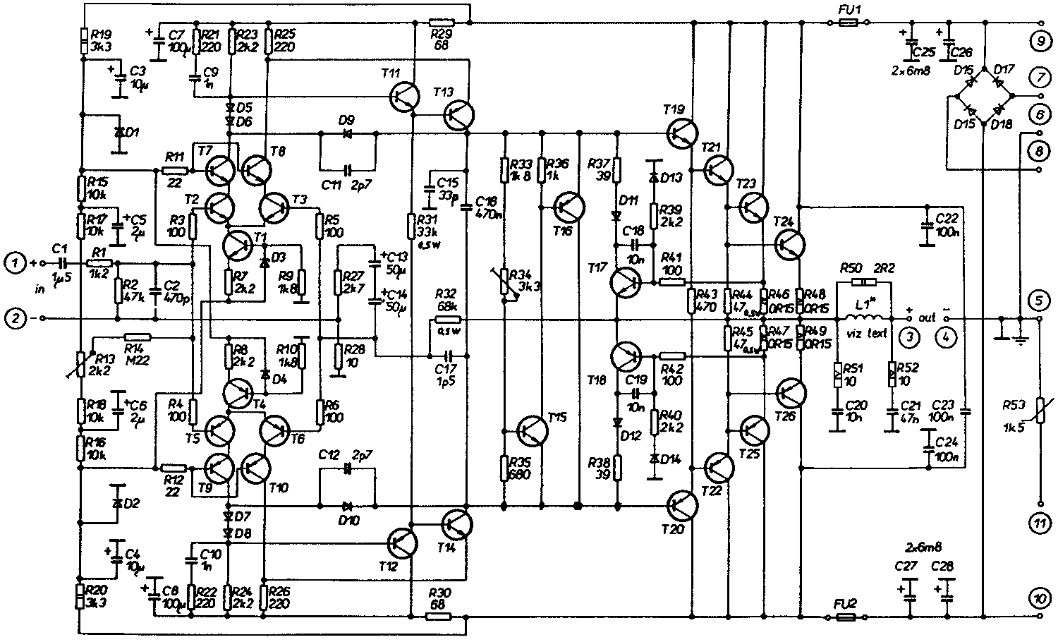
The DPA 440 low detail schematic (click on the image to see the high detailed
version (47 Kb)
Do not try to print this picture in Netscape because it's too big.
This amp is just a more powerful brother of the above. The
output transistors are not darlingtons anymore.
The bias current is 55 mA. The output coil is 16 turns of 1.5mm
wire on an 8mm diameter.
The best visible difference is seen in the input stage - the differential
amp has 5 transistors in each branch instead of three. The two additional
transistors, T7+T8 / T9+T10, take over the voltage, while the rest is
responsible for the amplification. The T1 to T6 don't have to carry the high
voltage and can be low-noise types, while T7 to T10 carry the voltage.
The author says there's another important advantage - this solution subdues
Miller's feedback CB capacities of the differential amplifiers which
improves slew rate and thus distortion on high frequencies.
Also the transistors of the differential amplifier work at a constant
voltage which improves linearity and th us contributes to lower distortion.
The trafo should be about 2*40 Volts and 12 to 15 Amps.